
Ing. Martin Pospíšilík, Ústav bezpečnostního inženýrství, FAI UTB, pospisilik@fai.utb.cz
doc. Mgr. Milan Adámek, Ph.D., Ústav bezpečnostního inženýrství, FAI UTB, adamek@fai.utb.cz
Anotace
Již déle než rok můžeme při zvláštních příležitostech v aule Fakulty aplikované informatiky potkat malou vzducholoď. Tento článek přináší čtenářům základní informace o tomto projektu, který se zabývá vývojem autonomního monitorovacího systému. Jedná se o zařízení schopné pohybu uvnitř uzavřené místnosti bez zásahu obsluhy, které je schopno monitorovat své okolí.
Abstract
For more than one year we can, at special occasions, meet an airship in the hall of Faculty of applied informatics. In this article, reader can find basic information about this project that is devoted to developing an autonomous monitoring system which is able to move inside an enclosed hall, monitoring his neighbourhood.
Introduction
First of all, let us mention a few words about airships and their usage as autonomous monitoring systems. For a long time airships seemed to be outdone but now they are experiencing a considerable renascence. Nowadays, we distinguish between two main groups of them: big ones for outdoor operation and small ones for indoor operation. Let us focus on the small ones that can operate inside buildings. They can be used for several purposes. They are good for advertisement because they attract the attention. But this is not our goal. We want to employ their physical advantages, mainly their capability to float in the air with minimal power consumption. Modern Li-Ion accumulators are advantageous to power small engines that move the airship, but do not have to have sufficient power to hold it in the air with all the equipment.
Airship at the UTB
The airship operating at the Faculty of Applied Informatics is custom-made modeller product that is capable to bear up to 650 g of load. Equipped with an RC controller, it can be driven like an aeromodel. The bladder is filled with helium, which makes the model operation rather expensive. Because the helium molecule is very small and tends to leak through the material of the bladder, the nominal volume of 2.7 m3 of the bladder must be checked weekly. The material of the bladder is a special foil made for airships, having a small weight per area unit in order not to decrease the load capability of the airship.
The goal of the project is to develop such kind of driving system that would be light enough to be carried by the airship and would be able to drive the airship automatically in order it could avoid obstacles. Such automatically driven airship should carry a web camera streaming the picture to the local area network.
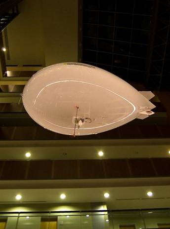
Fig. 1 Airship at the TBU
Design of the automatic monitoring system
The complex of the airship, the automatic driving system and the monitoring system can be generally called as the Automatic monitoring system. Development of this system is processed on several parts of this complex in parallel. There have been several kits developed in order to check the behaviour of particular parts of the system and some of them are still in progress. At the end, these kits shall be integrated into one complex driving system operating on one microcontroller.
Orientation – testing kit
Avoiding the obstacles is supposed to be assured by a set of 9 ultrasonic detectors. The block diagram of the kit is shown in Fig. 2. The CPU communicates via the I2C bus with 9 ultrasonic detectors that send back information about a distance to the obstacles. The typical sensitivity diagram of the detectors is shown in Fig. 3. The measured distance can be evaluated as a function of time and sound velocity, see equation (1). Because there is a need to detect an obstacle being at least 0.7 m off, we can neglect the dependence of the sound velocity in the air on many factors, mainly on the temperature, as displayed by equation (2).
![]()
Where:
T - time between sending and receiving the signal,
L - distance from the obstacle,
c - sound velocity.
![]()
Where:
c - sound velocity,
t
- air temperature.
Based on the information provided by the ultrasonic detectors, the CPU can estimate distances to the obstacles in the neighbourhood of the airship. These distances are displayed on the LCD display and if any of these distances is critical, proper LED belonging to the appropriate ultrasonic detector starts glowing. This information can be the processed for driving the motors.
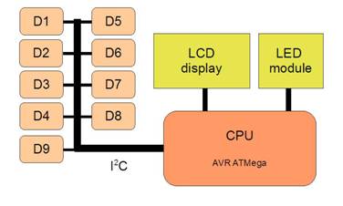
Fig. 2 Orientation testing kit
Fig. 3 Ultrasonic detectors sensitivity diagram
Motors driving kit
Presently, motors driving kit is under development. It should, according to the information gained through the orientation kit, drive the motors of the airship. The airship is pushed by two motors in a straight way while its turning is ensured by a small motor at the rear of its bladder. This motor is also used to stabilize the airship in a forward direction. Rotation of the tale is scanned by means of two accelerometers.
Monitoring kit
The first project deals with mounting a webcam to the airship. In Fig. 4 you can see a block diagram of the monitoring testing kit. If the WiFi router is connected to the local area network by means of the WiFi technology, through the proper web application the user can see a picture picked by the webcam. Moreover, via the application the user has a possibility to send some commands back to the airship. These commands are then explicated by force of the IP relay and can be delivered to the processing unit at the airship. Appearance of the web application can be seen in Fig. 5.
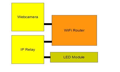
Fig. 4 Monitoring kit
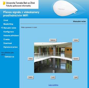
Fig. 5 Web application for WiFi communication with the airship
Power supply
For distribution of energy from the accumulator battery there is a need of a switching power supply, which has low weight, is capable of delivering sufficient current and to protect the accumulator from a deep discharge. Because inside the battery there are two accumulators connected in a serial way and they can have different characteristics, each accumulator must be scanned separately. The power supply module transforms the accumulator voltage of 7.4 V to 5 V needed to feed microcontrollers and logical circuits and 12 V needed to feed a web cam and some other appliances. The schematics of the power supply can be seen in Fig. 6.
The accumulator is connected to X1 and can be disconnected by means of a small relay K1 driven by a system of comparators IC3A to IC3D if one of the accumulator cells gets discharged. Step-up and step-down converters are employing low-cost and easy applicable integrated circuits MC34063.
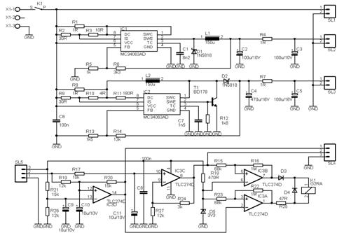
Fig. 6 Power supply schematics
Target state
At the end all the functionary kits will be integrated onto one board employing one CPU. A block diagram of such board can be seen in Fig. 7.
Fig. 7 Block diagram of the target state
Conclusion
Within the framework of the project, above mentioned kits are developed and tested for their proper functionality. The project is quite complex, solving problems related to mechanics, communication, electronics and microcontrollers programming.
The project is supported by Internal Grant Agency of Tomas Bata University, IGA/45/FAI/10/D.
Literature
MAHDAL, M. Wireless Technologies and Their Applications. In 9th International Carpathian Control Conference ICCC´2008. Sinaia, Romania, May 25 - 28, 2008, pp. 388 – 391. ISBN 978-973-746-897-0.
FORMÁNEK, I. Základy automatizace. Logické řízení. 1. vyd. Ostrava : VŠB-TU Ostrava, 2006. 86 s. ISBN 80-248-1012-3.
BABIUCH, M. Implementation of User-friendly Programming Environment for Standalone Micro-controllers. In Proceedings of 3rd International Carpathian Control Conference. Ostrava : VŠB-TU Ostrava, 27. - 30. 5. 2002, p. 471-475. ISBN 80-248-0089-6.
NOVÁK, P. 2007. Mobilní roboty, 1. díl, Praha: BEN – technická literatura, 2007, 248 p., ISBN 80-7300-140-1.
ĎAĎO, S., KREIDL, M. 1999. Senzory a měřicí obvody, Praha: Vydavatelství ČVUT, 1999, 315p., ISBN 80-01-02057-6.
CHUDÝ, V., PALENČÁR, R., KUREKOVÁ, E., HALAJ, M. 1999. Meranie technických veličín, Bratislava: Vydavateľstvo STU, 1999, 672 p., ISBN 80-227-1275-2
FRADEN, J. 2004. Handbook of modern sensors, New York: Springer-Verlag, Inc., 2004, 589 p., ISBN 0-387-00750-4.
POSPISILIK, M., ADAMEK, M. 2009. Autonomous Airship. In Transactions of the VŠB – Technical University of Ostrava, Mechanical Series, color="black">No. 2, 2009, vol. LV, Ostrava, Czech Republic, pp 109 – 114, ISBN 978-80-248-2144-3.
POSPISILIK, M., PUCHAR, J., ADAMEK, M. 2009. WiFi Module for Autonomous Monitoring System. In The 20th INTERNATIONAL DAAAM SYMPOSIUM. Vienna, Austria, pp 1325 – 26, ISSN 1726-9679.
POSPISILIK, M., ADAMEK, M. 2009. Autonomous Monitoring System. In 13th International Research/Expert Conference TMT2009. Hammamet, Tunisia, pp 777 – 780, ISSN 1840494.
POSPISILIK, M., ADAMEK, M. 2009. Autonomous Airship As A Surrounding Monitor. In XXXIV. Seminar ASR 2009. Ostrava, Czech Republic, pp 277 - 284, ISBN 978 - 80 - 248 - 1953 - 2
Aktuální číslo
Odborný vědecký časopis Trilobit | © 2009 - 2026 Fakulta aplikované informatiky UTB ve Zlíně | ISSN 1804-1795