
Martin Pospíšilík
Ústav počítačových a komunikačních systémů
Fakulta aplikované informatiky
Univerzita Tomáše Bati ve Zlíně
pospisilik@fai.utb.cz
Abstrakt: Článek obsahuje popis konstrukce elektrického obvodu, který slouží jako interface pro optickou závoru. Obvod byl původně vyvinutý pro snímání otáček klikového hřídele zážehového motoru, obecně jej však lze využít vjakékoliv aplikaci, kde je třeba přesné měření otáček, případně zjišťovat průchod mechanického prvku určitým bodem trajektorie.
Klíčová slova: Štěrbinový přerušovač, optická závora, snímání rychlosti hřídele
Abstract: This paper provides a description of a construction of an electrical circuit that operates as a fast interface for a photocell module. Although originally developed for a gasoline engine crankshaft position sensing, it can be applied in various situations when accurate angular shaft velocity sensing as well as a point of time in which a monitored object matched the defined position detection etc.
Keywords: Slotted interrupter, photo cell, shaft velocity sensing
1. Introduction
Different types of photocells are easy to purchase. Many of them operate as a slotted interrupter on a principle depicted in Fig. 1.
Fig. 1. Slotted interrupter principle [2]
The slotted interrupter consists of a plastic holder with a slot that bears a LED diode and a photo transistor. The optical coupling between the diode and the transistor is ensured via a thin slot. If an object is inserted in the slot, the coupling is interrupted. Typical applications of this device are as follows: speed control, motor control, monitoring of paper feed in printers, copiers or facsimiles, control of print head in printers, coin detection, optoelectronic switches and so on.
The issue is to make the reaction on the appearance of a mechanical object in the slot as fast and accurate as possible. Therefore the circuit described in this paper was constructed, being small enough to create a compact unit together with the slotted interrupter, with the photo sensor operating in a current mode, excluding the influence of parasitic capacities.
2. The construction
SFH9302 [2] slotted interrupter was utilized for the purposes of this construction. For its dimensions it is suitable for angular speed of a flat disc sensing. Typically a wreath mounted on the sensed shaft is applicable. The slotted interrupter is mounted on a printed circuit board together with the interface circuitry the schematic diagram of is depicted in Fig. 2.
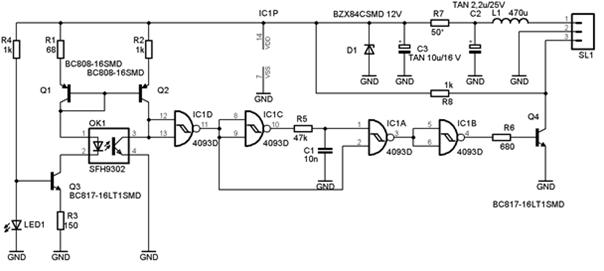
Fig. 2. Slotted interrupter interface circuit diagram
The power supply delivery is, together with the output signal, provided through one connector, numbered as SL1. Because operation in a motor vehicle was supposed, internal voltage stabilization consisting of R7 resistor and D1 Zener diode was implemented. The supply voltage level is not critical, but these devices were intended to protect the circuitry from voltage surges that can occur in the power network of the vehicle. However, the power supply voltage should lie between 10 and 15 V.
The slotted interrupter OK1 is fed by means of a current mirror that utilizes BJT transistors Q1 and Q2. The photo emitter is supplied with a current the level of which is stabilized at 10 mA by means of a current sink consisting of Q3 transistor, R3 resistor and LED1. Therefore it is strictly advised the threshold voltage of LED1 was 2.2 V. If not, the value of R3 resistor must be adjusted appropriately. The current mirror ratio is defined by the ratio of the resistor values R1 and R2. With the values in the schematics, the current through the detector is limited to approximately 750 µA. As the current transfer ratio of the photo cell is 0.1 [2], the estimated current through the detector would be approximately 1 mA provided the optical coupling is not interrupted by any mechanical part. As the result, the collector voltage of the photo detector is very low, typically under 1 V, which drives the Schmitt invertor IC1D to the H state. When the optical coupling is interrupted and the current through the detector drops below 750 µA, the collector voltage of the detector rises rapidly as the current source utilizing the Q2 transistor tries to push the current through it. Simultaneously, the utilization of the Schmitt NAND gates ensures that the circuit is insensitive to small voltage ringing.
Once the optical coupling interruption is detected, a negative pulse of a defined width is generated. This is ensured by the monostable circuit consisting of IC1C and IC1A Schmitt NAND gates. The time constant of the monostable circuit is approximately given by the following equation:
![]()
For the values indicated in the schematic diagram the time constant is approximately 300 µs which is enough to drive the output transistor Q4 high, generating the L pulse at the output of the circuit.
The mechanical construction is quite easy, as the circuit is built on a single-layer printed circuit board the dimensions of which are 34 x 17 mm. Except OK1, SL1 and L1 all devices are of SMD type. The devices displacement can be found in Fig. 3 while the printed circuit board layout is depicted in Fig. 4.
Fig. 3. SMD devices displacement
Fig. 4. Printed circuit board outline
3. Practical experience
The circuit described in this paper was tested, being utilized as gasoline engine crankshaft angular velocity sensor. The maximum angular velocity of 6,000 rpm was reached, providing four pulses per one revolution. The output pulses were approximately 300 µs wide, generated at the frequency of 400 Hz. The typical output at 6,000 rpm is depicted in Fig. 5.
The estimated maximum operating frequency is 1.5 kHz, responding to the angular velocity of 90,000 rpm provided one pulse per one revolution is generated.
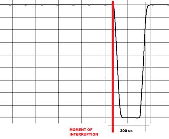
Fig. 5 – Typical output signal
4. Conclusion
This paper describes the construction of the simple electrical circuit that operates as an interface to a slotted interrupter. At the position of the slotted interrupter, SFH9302 photo cell was employed, being insensitive to ambient lighting. Although the circuit was originally considered to operate as a gasoline engine crankshaft angular velocity sensor, thanks to its fast response it can be used in many applications where angular velocity measuring or accurate position of a mechanical element sensing is needed, e.g. mechanical machines synchronization, angular velocity sensing in systems with advanced feedback-based controlling, etc. Last, but not least, the described sensing unit can be used in laboratory experiments from the field of controlling for sensing of robot velocity, its arms position (by incremental counting) or other similar applications.
References
[1] BRTNÍK, B., Číslicové systémy, BEN – Technická literatura, 2011, 169 s.,
ISBN 978-80-7300-4.
[2] OSRAM Gmbh, SFH9302 datasheet, available online:
http://www.datasheetarchive.com/SFH9302-datasheet.html
[3] FRADEN, J., Handbook of modern sensors, New York: Springer-Verlag, Inc., 2004,
589s., ISBN 0-387-00750-4.
[4] ZÁHLAVA, Vít, VOBECKÝ, Jan. Elektronika : Součástky
a obvody, principy a příklady. Praha : Grada Publishing, 2001. 192 s. ISBN 80-7169-844-9.
Aktuální číslo
Odborný vědecký časopis Trilobit | © 2009 - 2026 Fakulta aplikované informatiky UTB ve Zlíně | ISSN 1804-1795