
Ing. Martin Pospíšilík
Ústav počítačových a komunikačních systémů
Fakulta aplikované informatiky
Univerzita Tomáše Bati ve Zlíně
pospisilik@fai.utb.cz
Abstract: Distance measurement belongs to the oldest humans’ tasks. However, it is still an evolving discipline that includes up to 25 % of all industrial measurements performed under discrete processes. Aside traditional methods the proximity distance measurement methods are evolved. In some cases these methods are the only applicable ones. For example, the ultrasonic proximity distance measurement is embedded in robots, unmanned flying vehicles etc. In this paper the principle of the ultrasonic proximity distance measurement is described as well as the experience with utilizing this method to detect obstacles around the autonomously operating airship.
Keywords: Ultrasonic detectors, Proximity distance measurement, Autonomous airship
Abstrakt: Ačkoliv měření vzdálenosti patří mezi nejstarší měřičské disciplíny, navzdory prudkému rozvoji technologií a měření všech různých veličin si na všech člověkem prováděných měřeních stále zachovává asi 25% podíl. Kromě tradičních metod měření vzdálenosti se v současné době uplatňují i bezdotyková měření, přičemž vněkterých případech tradiční měřicí metody ani nelze uplatnit. Jako příklad lze uvést vzdálenostní detektory, kterými bývají opatřeni roboti, bezpilotní letouny a další zařízení. Tento článek se věnuje popisu principu ultrazvukových měřičů vzdálenosti a zároveň popisuje zkušenosti svyužitím těchto měřičů na autonomně pracující vzducholodi.
Klíčová slova: Ultrazvukové detektory, Bezdotykové měření vzdálenosti, Autonomně pracující vzducholoď
1 Introduction
The ultrasonic proximity detectors are easily applicable devices that allow to measure distance from any object that lies perpendicular to their radiation beam. Although their accuracy can be affected by many influences, in some cases they are the only constructer’s choice. The main reason is that apart from the optical proximity detectors the ultrasonic proximity detectors can operate in various environments regardless to the light absorption of the surface of the measured object.
The main advantage of ultrasonic distance meters are as follows:
For these reasons the ultrasonic detectors were utilized in the project of Autonomous monitoring system that consists of a monitoring device mounted on an airship that is capable of independent operation inside an enclosed hall. The set of ultrasonic detectors ensures that the airship detects obstacles in its neighbourhood and therefore can change its trajectory in order it avoided a pertinent collision.
2 Ultrasonic distance meters principle
Usually, ceramic resonant transducers operating with the frequency of approximately 40 kHz are employed, using a narrowband signal. Their bandwidth is usually limited to no more than 2.5 kHz [1]. Several periods of sonic signal are emitted to the obstacle, being reflected back to the receiver within a delay that is defined by the velocity of the sound in the air and the distance between the meter and the obstacle. The received signal is then analysed in order one could decide whether it is the reflection of the transmitted signal or only a noise from the surroundings.
In the ceramic resonant transducers piezoelectric effect is employed, based on the fact that a crystal deformation results in the change of its surface charge and vice versa. This effect is quite intensive with crystals that are not centrally symmetrical. The required resonant frequency can be achieved by optimization of the crystal dimensions. Therefore synthetic ceramics is widely used for these purposes as its characteristics can be determined during its production. Currently, materials on the basis of solid solutions of leaded zirconate (PbZrO2) and leaded titanate (PbTiO2) with the addition on Sr, Ba, Ca, Bi, Sb and W are most widely used. [1]
Of course, there are also several disadvantages arising from the ultrasonic distance meters utilization. First of all, the sound velocity in the air differs according to the elevation and to the temperature. It can also be affected by the atmospheric pressure variations. Secondly, accurate clock source must be employed in the ultrasonic distance meter because the distance (length) is generally a function of sound velocity and time. Considering the air to be an ideal gas, the following equation can be applied in order to determine the measured distance lm:

Where:
κ - Poisson’s constant,
ρg0 - gas (air) density at 0°C (273.15 K) [![]() ],
],
pg0 - gas (air) pressure at 0°C (273.15 K) [Pa],
γg - coefficient of the gas (air) thermal expansiveness [![]() ],
],
tg - air temperature [K],
T - time period between the sent and the received signal [s].
A partial compensation of the measurement error caused by the changes of the above mentioned parameters can be established when there is also an accurate temperature measurement. The following approximation can be established. Considering the zero elevation and typical air pressure and density, the equation (1) can be approximated by the following one:
![]()
According to (2) it can be deduced that once the temperature changed by 25 °C, the measurement error increases by 5 %.
Other problems occurring with method of measurement are caused by the shape of the emitted signal. In a plane, instead of an ideal straight line, the energy of the emitted signal is in front of the transmitter displaced according to Fig. 1. In practice this leads to the effect depicted in Fig. 2. In case the detector does not form a right angle with the measured surface, the shortest way of the emitted and received signal is not the expected red line, but the blue line, being placed at the border of the transmitting diagram. The situation can be analysed by employing the Sine theorem. If supposed the transmitting angle of the ultrasonic distance meter is α and the angle between the detector orientation and the measured surface is β, then a triangle consisting of the red and blue lines and part of the surface (black) can be identified. From the triangle theory the angles inside the triangle are α/2, β and γ = 180 – (β+α/2). When the Sine theorem is applied, the equation (3) can be used to estimate the distance that was really measured. However, this is only a rough approximation, not considering the real shape of the emitted acoustical signal. Moreover, the approximation is valid only if γ = 180 – (β+α/2) > 90°. Otherwise the measurement will be correct.
![]()
Fig. 1 – Typical ultrasonic transmitter radiation diagram [2]
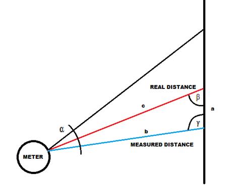
Fig. 2 – Measurement error caused by non-perpendicular reflection
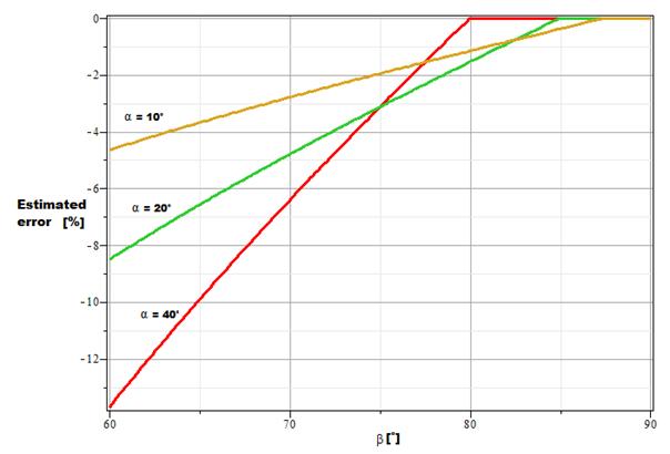
Fig. 3 – Error caused by the mutual geometry of the measured object and the surface of the obstacle (computed in mathematical software, see text).
In Fig. 3 practical issues arising from equation (3) are depicted. On the x-axis the angle between the detector plane and the surface is considered, on the y-axis the estimated error according to (3) is depicted for ultrasonic detectors of different radiation angles (10°, 20° and 40°). It is obvious that detectors with wider radiation angles allow to measure in wider angle with almost no error (± 10°), but once the critical angle is overpassed, the error increases rapidly. Advanced detectors employ a complex algorithm that allows, by changing the irradiation power, change the shape of the emitted signal and consequently obtain better accuracy when the measurement is processed under various angles.
Another disadvantage that must be considered at the orientation system of the airship is the fact that the performance of the ultrasonic detectors is dependent on the attenuation of the signal caused by the structure of the measured material. Almost all materials reflect the sound properly but the surface geometry of some of them may cause the reflections are directed not back to the receiver, but in other direction. Therefore poor performance may be observed if the obstacles are including cylindrical or conical surface. In addition, the 40 kHz sound waves are only 8.5 mm long so corrugated or perforated surfaces can cause high attenuation of the sound.
When more ultrasonic detectors are employed, their time synchronization is crucial. Usually it is obtained by a microcontroller that also evaluates the outputs of the detectors.
Current detectors usually achieve a good performance in the distance range from 0.1 to 6 m, providing linearity better than 0.2 % and uncertainty on the order of percent. Connection among the microcontroller and the set of the detectors is usually established my means of the I2C bus. An example of SRF05 ultrasonic detector is depicted in Fig. 4.
Fig. 4 – Ultrasonic detector example
3 Practical experienceFor the purposes of the experience gaining a testing kit was created. Its block diagram is depicted in Fig. 5.
Fig. 5 – Ultrasonic detectors testing kit
This testing kit simulates the anti-collision system to be implemented in the autonomously operating airship. It is based on a microcontroller that communicates with up to 9 detectors by means of the I2C bus. The microcontroller periodically processes the information gathered from all the connected ultrasonic detectors and displays the appropriate measured distances on a display. Moreover a LED indicator was added to simply inform that there is an obstacle in front of any of the detectors.
This kit for obstacles detection was utilized in several tasks arranged in order the accuracy and reliability of the ultrasonic detectors was proven. The purpose of these tasks was to claim the appropriateness of the ultrasonic detectors for obstacles detection the accuracy of which is, considering the utilization of this method by the Autonomous monitoring system, critical. By these tests it has been confirmed that in most cases the ultrasonic detectors are accurate and reliable enough to be employed for detecting the obstacles around the airship of the Autonomous monitoring system.
In accordance to the theory described in the theoretical part of this paper, the accuracy of the detection was affected by the ineligible width of the transmitted ultrasonic beam and the receiving characteristics of the ultrasonic detectors (see Fig. 1). However, when the inaccuracy of this type was observed, the measured distance was usually shorter than the real one, which does not affect the obstacles detection. The only consequence of such inaccuracies is that the obstacle is detected sooner or that spurious obstacle is detected. The above mentioned inaccuracies occur in the following cases:
a) the obstacle is not perpendicular to the axis of the ultrasonic beam,
b) there are other obstacles around the ultrasonic detector than the one to which the detector is directed being on the periphery of the ultrasonic beam, causing spurious reflections of the ultrasonic signal.
Whereas the above mentioned inaccuracies do not have a negative influence to the obstacles detection, unfortunately, there exist rare cases in which the detectors fail. The fail of the detectors occur when the surface of the obstacle attenuates the ultrasonic signal considerably or when the surface of the obstacle is too small in comparison with the transmitted ultrasonic beam width. Then the following problems can occur:
a) the range of the detector is decreased,
b) the detector does not detect the obstacle at all.
The results of the measurements obtained by the Module for obstacles detection are as follows:
a) metal column with a diameter of 75 mm was detected at a distance of 3.5 m,
b) paper box of dimensions 22 x 25 x 25 cm was detected at a distance up to 6 m,
c) aluminium foil coated target of dimensions 10 x 10 cm was detected at a distance of 5.16 m,
d) aluminium foil coated target of dimensions 20 x 20 cm was detected at a distance of 6.51 m,
e) wooden stick with a diameter of 12 mm was not detected at all, presumably due to scattering of the sound beam into the surroundings.
The inaccuracy of all the above mentioned measurements was lower than ± 2 cm.
Because in the area in which the operation of the Autonomous monitoring system is supposed there are several sound-absorbing sidings operating on the principle of Helmholtz resonators, the ultrasonic detectors were also tested on detecting these surfaces. The sound-absorbing sidings consist of performed plates, employing sound-absorbing material in the perforations. The sound absorption is efficient especially at high frequencies, making the ultrasonic detection difficult. The results obtained when detecting the sound-absorbing sidings were fluctuating according to the angle between the beam and the surface and the point on the surface at which the ultrasonic beam was aimed to. When aimed between the perforations, the ultrasonic detectors operated satisfactorily, having the maximum operating range decreased only. When aimed directly to the perforation, the detectors failed. However it is assumed that the detectors can detect the sound-absorbing surfaces with good reliability due to the fact that the Autonomous monitoring system is moving against their surface, resulting in the acoustic beam angle and position variation in time. Therefore it is expected that some of the reflections from the surface will be detected properly.
In the text below the results of more systematic accuracy measurements are provided. The accuracy of the distance measurement was proven by measuring the distance from a flat wall and from a wooden column under various angles (60°, 90° and 120°).
The results obtained at measuring the distance from the flat wall are depicted in Fig. 6. The real distance measured manually is displayed on the x-axis while the distance measured by the ultrasonic detectors is depicted in the y-axis. The green line represents the ideally linear relationship between the results of both measurements. The blue line represents the results obtained when the acoustic beam was perpendicular to the wall while the red line represents the results when the acoustic beam clutched with the wall the angle of 120° or 60° respectively (the results for 60° and 120° were identical). It is obvious that for distances higher than 0.4 m and perpendicular acoustic beam to the measured surface the results delivered by the ultrasonic detectors are greatly close to the ideal characteristics while provided the acoustic beam is not perpendicular to the measured surface, the results show a considerable error. For 30° difference from the right angle the error caused by the reflection of the lateral sections of the acoustic beam is approximately – 10 %. The consequence of this phenomenon results in the fact that large flat areas, like walls etc., may be detected as closer than they really are. However, this is not considered as a malfunction of the obstacle detection system.
Other measurements were processed with a wooden column having a rectangular cross-section of approximately 0.24 x 0.6 m. The results are depicted in Fig. 7. The same angles as in the previous measurement were applied. Also the graph elements are formatted in the same way as those depicted at Fig. 6. In this measurement the results were greatly accurate for all applied angles between the detectors and the measured object. This is a consequence of the fact that the area of the object’s surface is limited, not allowing reflections of the lateral sections of the acoustic beam.
Fig. 6 – Distance from the flat wall measurement results (see text above)
Fig. 7 – Distance from the wooden column measurement results (see text above)
4 ConclusionOn the basis of the above mentioned results it can be claimed that the ultrasonic detectors in the proven configuration are suitable for detecting the obstacles in the surroundings of the Autonomous monitoring system. They are reliable and accurate. In most cases the inaccuracy was lower than ± 2 % which is sufficient, especially if there is a need to detect obstacles in the distance of approximately 1.5 m.
It is also worth mentioning that the weight of the whole obstacle detection system can be quite low which is very important if such a system is to be embedded to a small airship the load capacity of which is limited.
The worst disadvantage is that the reliability of the detectors is decreased if the measured object absorbs the ultrasonic waves heavily. However, there are not many materials with such capabilities of absorption.
Acknowledgement
This paper is supported by the European Regional Development Fund under the project CEBIA-Tech No. CZ.1.05/2.1.00/03.0089.
5 References
[1] CHUDÝ, V., PALENČÁR, R., KUREKOVÁ, E., HALAJ, M., Meranie technických veličín, Bratislava: Vydavateľstvo STU, 1999, 672s., ISBN 80-227-1275-2
[2] SRF05 – datasheet
[3] FRADEN, J., Handbook of modern sensors, New York: Springer-Verlag, Inc., 2004, 589s., ISBN 0-387-00750-4.
[4] ZÁHLAVA, Vít, VOBECKÝ, Jan. Elektronika : Součástky a obvody, principy a příklady. Praha : Grada Publishing, 2001. 192 s. ISBN 80-7169-844-9.
Aktuální číslo
Odborný vědecký časopis Trilobit | © 2009 - 2026 Fakulta aplikované informatiky UTB ve Zlíně | ISSN 1804-1795